LESSONS FROM MISSION-CRITICAL ELECTRICAL INFRASTRUCTURE COMMISSIONING

Applying testing, validation, and commissioning best practices to improve reliability and reduce operational risk.

SYSTEM DESIGN ELEMENTS
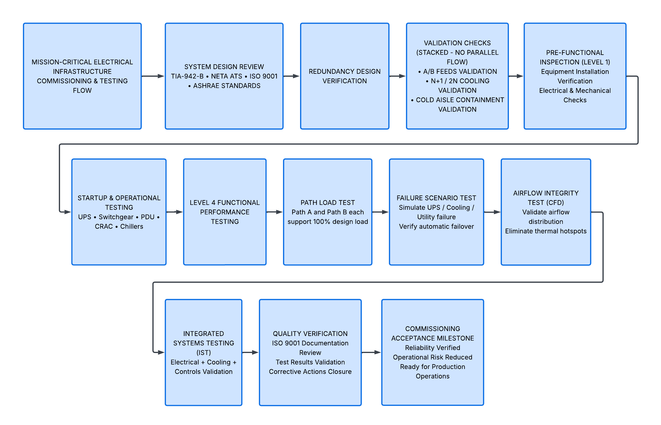
The diagram includes the following redundancy features:
• A/B Redundant Feed: Two independent paths sourced from separate UPS and cooling systems, ensuring no shared single point of failure.
• Redundant Cooling Units (N+1 / 2N): Additional CRAC or chiller capacity ensures continuous operation during maintenance or equipment failure, following TIA-942-B Tier design principles.
• Cold Aisle Containment: Physical barriers such as glass or PVC curtains maintain airflow separation and prevent hot air recirculation.

THE MARKUP: VERIFICATION AND MILESTONES
The diagram includes structured commissioning checkpoints aligned with NETA ATS testing standards and ISO 9001 quality verification processes.
BLUE CALLOUTS: WITNESSING AND VERIFICATION
Blue callouts represent Level 4 Functional Performance Testing (FPT) milestones. These are formal verification stages where systems are tested under real operating conditions.
Key verification activities include:
• Path Load Test: Each A or B path is validated to independently carry 100% of design load, ensuring full redundancy.
• Failure Scenario Test: Simulated failures confirm automatic failover between systems without service interruption.
• Airflow Integrity Testing: Computational Fluid Dynamics (CFD) modeling verifies proper airflow distribution and eliminates thermal hotspots.
CFD is a simulation method used to analyze how air moves within enclosed environments, ensuring compliance with ASHRAE thermal guidelines.