FAIL-SAFE SCADA ARCHITECTURE FOR CRITICAL INFRASTRUCTURE

Designing resilient infrastructure that continues operating during failures and unexpected events.

THE LAYOUT: A/B DISTRIBUTION AND CONTAINMENT
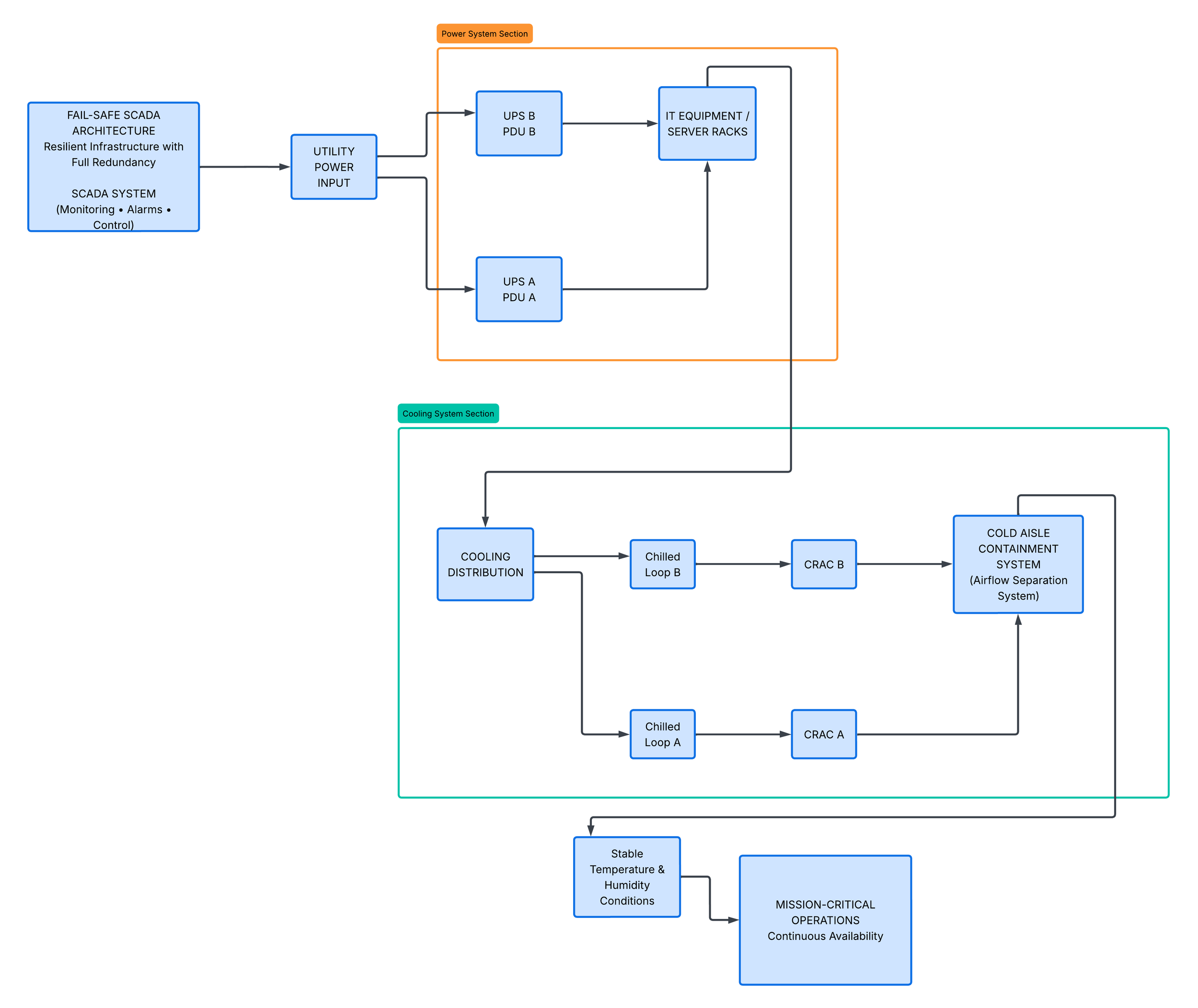
The diagram follows TIA-942-B standards for redundant data center infrastructure design. It illustrates two mirrored pathways, labeled Path A and Path B, to ensure full physical redundancy in both power and cooling systems.
A/B Distribution is a redundancy model where two independent systems deliver continuous service even during failure. This approach aligns with ISO 9001 quality principles and ASHRAE environmental reliability standards for mission-critical environments.
POWER DISTRIBUTION
For power distribution, Path A and Path B originate from independent UPS systems. UPS systems provide backup electrical power during utility failure or instability. Each path follows diverse and physically separated routes to independent PDUs.
PDUs (Power Distribution Units) distribute electrical power safely to multiple IT equipment racks. Physical separation ensures that a single failure cannot impact both power paths, improving system resilience.

COOLING DISTRIBUTION
For cooling distribution, mirrored chilled water loops supply CRAC units across the facility. CRAC units are precision cooling systems designed to maintain stable temperature and humidity conditions for IT loads.
These systems feed into cold aisle containment structures, which are engineered barriers that separate cold intake air from hot exhaust air. This separation improves cooling efficiency and supports ASHRAE recommended operating ranges for data centers.
Containment systems maintain airflow discipline and reduce energy waste. This directly improves thermal stability and reduces risk of overheating events.